Mechanical engineering services connect Product Lifecycle Management (PLM) strategy with the structural decisions that determine how a product is designed, built, and maintained.
PLM serves as the foundational backbone for product data management from inception to retirement. However, its performance is strictly governed by the accuracy and organization of the engineering data fed into it.
This blog explains how mechanical engineering supports each lifecycle stage by shaping design, manufacturing, and quality. Also discover how it helps businesses minimize rework, cost, and time-to-market.
Key Takeaways
|
How Mechanical Engineering Services Support the Product Lifecycle
Mechanical engineering supports the product lifecycle by creating, validating, and maintaining the physical design data that are governed by PLM systems. PLM is the practice of managing product information, processes, and people from concept through service and retirement.
The challenge is that the software alone cannot fulfil that scope, because the records it stores originate in engineering work.
Mechanical design services supply the CAD models, drawings, Bills of Materials (BOM), and specifications that give a PLM environment its essential structure, and they keep that integrity consistent as designs change. The product lifecycle also depends on a shared product model. The table below summarizes their contribution at each lifecycle stage:
|
Lifecycle Stage |
Mechanical Engineering Contribution |
PLM Output |
|
Concept |
Feasibility studies and requirement translation |
Requirements baseline |
|
Detailed design |
3D modeling, tolerancing, and material selection |
Released CAD data and engineering BOM |
|
Validation |
Structural, thermal, and motion analysis |
Verified design records |
|
Manufacturing planning |
Design for manufacturability and process definition |
Manufacturing BOM and work instructions |
|
Service and retirement |
Root-cause analysis and change input |
As-maintained history and change requests |
Each stage feeds the next, so gaps in early data create errors that surface later in production and service.
The Role of Mechanical Engineering in Design, Manufacturing, and Product Quality
Mechanical engineering can be seen as a ‘pre-processing step’ that determines product quality by defining geometry, tolerances, materials, and assembly methods before the beginning of production. These choices address most of a product’s manufacturing cost and performance characteristics, which is why they require structured review.
Three areas reflect this influence most clearly:
- Design: Simulation and design-for-manufacturability checks confirm that a component performs as intended and can be produced with available processes.
- Manufacturing: Accurate tolerance specifications and assembly sequences allow production teams to plan tooling and process steps without interpreting ambiguous drawings.
- Quality: Controlled revisions and traceable requirements ensure that inspectors and suppliers work to the current released design.
Organizations that position mechanical engineering services at the center of their PLM implementation gain a discipline software can’t provide on its own: seasoned mechanical engineers who understand how a part is made, measured, and assembled.
Also Read: Accelerating Product Development Through Mechanical Engineering Solutions
Mechanical Engineering’s Impact on Rework, Cost, and Time-to-Market
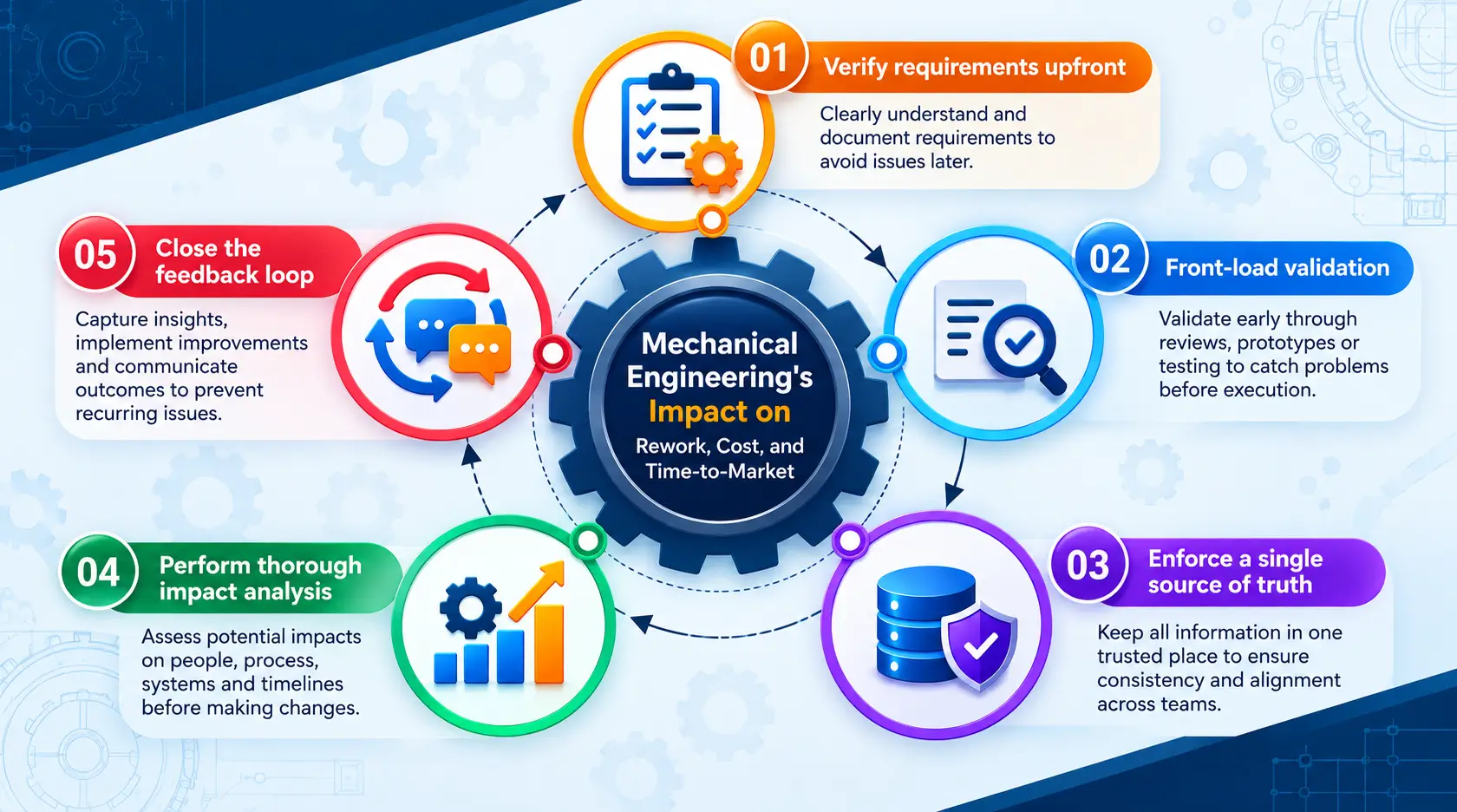
Mechanical engineering reduces rework, cost, and time-to-market by resolving design errors at the early stage, when correction is least expensive. Late-stage changes multiply expenses because they affect tooling, procurement, and documentation simultaneously.
A practical sequence for reducing rework includes the following steps:
- Verify requirements upfront: Eliminate costly design iterations by validating functional specifications before 3D modeling starts.
- Front-load validation: Conduct thorough FEA/CFD simulation and Design for Manufacturability (DFM) reviews prior to drawing release.
- Enforce a single source of truth: Maintain a centralized, controlled Bill of Materials (BOM) synchronized directly with manufacturing.
- Perform thorough impact analysis: Evaluate the downstream cost, tooling, and schedule impact of every engineering change order (ECO) before sign-off.
- Close the feedback loop: Feed field service, quality, and failure data back to the engineering team to drive continuous improvement in future revisions.
Each step shortens the path between design intent and a producible product. The cumulative effect is fewer prototype iterations, fewer engineering change orders, and more predictable launch schedules.
Conclusion
Mechanical engineering provides PLM its foundation by supplying accurate, traceable, and manufacturable design data at every lifecycle stage. PLM platforms manage information, but engineers determine whether that information is correct, reusable, and production-ready. Organizations that merge these two disciplines can substantially reduce rework, shorten development cycles, and retain design knowledge.
A practical starting point is assessing CAD structure, BOM alignment, and change control. Dansob provides mechanical engineering services that support this transition, including design development, simulation, and manufacturability checks, so leaders can identify lifecycle gaps before making wider commitments.
Also Read: How Modeling and Drafting Optimize the Engineering Design Process
FAQs
-
What is the Difference Between PDM and PLM?
Product data management (PDM) controls engineering files, revisions, and release status. PLM covers the full lifecycle, including requirements, manufacturing, supply chain, and service, and it uses PDM data as one of its inputs.
-
When Should a Manufacturer Involve a Mechanical Design Services Company in a PLM Project?
Engagement is most effective before data migration or process configuration begins. At that point, the engineer can define part structures, naming conventions, and BOM logic that the PLM system will enforce for years.
-
Can an External Mechanical Design Services Provider Work Within an Existing PLM System?
Yes, as long as the provider follows the client’s CAD standards, naming rules, and release workflows. Buyers should confirm how the provider handles revision control and data handover before work starts.
-
Which Metrics Show Whether Engineering is Improving Lifecycle Performance?
Useful indicators include the number of engineering change orders per release, BOM accuracy at handoff, first-pass manufacturing yield, and design cycle time. Tracking these over several projects shows whether improvements are sustained.
-
How Does Mechanical Engineering Connect With Systems, Electrical, and Software Teams?
Mechanical engineers work from the same requirements and configuration records as other disciplines. A shared PLM model keeps interfaces, dimensions, and change decisions visible to every team involved.